در اینجا مدارات منایع تغذیه رو قرار میدیم.

 توجه: این یک موضوع قدیمی است که آخرین پست ارسالی آن مربوط به 3933 روز قبل است . لطفا فقط پاسخ ها ، سوالات و درخواست های 100 درصد مرتبط را به آن ارسال کنید و برای درخواست ها و سوالات جدید موضوع جدیدی را ایجاد کنید


در اینجا مدارات منایع تغذیه رو قرار میدیم.
3.6 Travel Adapter
http://www.up.iranblog.com/images/9b...t50tf7ykei.rar
ویرایش توسط javad naderi : 05-05-2011 در ساعت 23:18

سلام
مدار منبع تغذیه های 0-40 ولت رومیزی موجود در بازار که با ترانس چند ولتاژی و 2n3055 کار میکنه را ندارید ؟
ممنون
سلام.همون 0 تا 50 ولته هم رو میزی و با 2n3055 هستش.
سلام
اون مدل منبع تغذیه ای رو میگم که ترانسش باید چند ولتاژ مختلف داشته باشه و متناسب با تنظیم ولتاژ با سوئیچ کردن هر رله یک ولتاژ ac را به ورودی اعمال میکنه
سلام
فکر میکنم منظور من رو متوجه نشده باشید
منبع تغذیه های رو میزی دارای چند رله هستن و متناسب با ولتاژ خروجی روی یکی از ولتاژهای ترانس سوئیچ میکنند . یعنی ترانس آنها چند ولتاژ خروجی داره نه یک ولتاژ .
اگر مدار اون را دارید ممنون میشم کمکم کنید .
لطفا شماتیک اون رو با فرمت پروتل بدید .
باتشکر
سلام.میدونم شما منظورتون ترانس های چند حالته هست.اوکی میزارم براتون.نوشته اصلی توسط havas

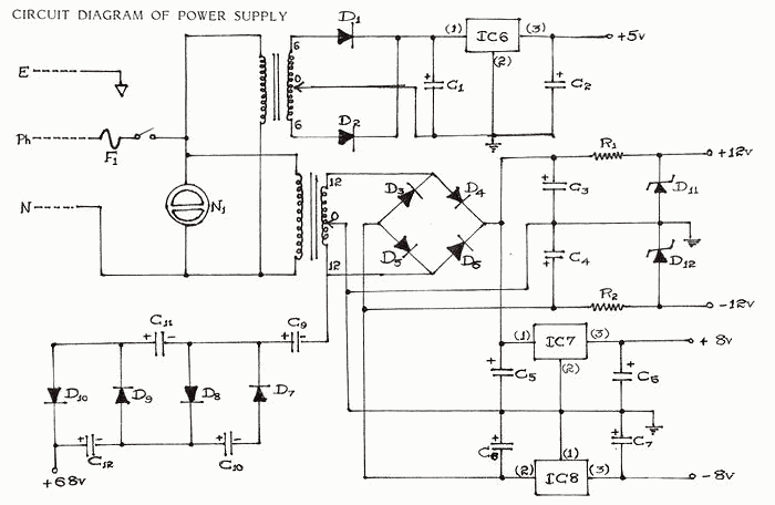
Multi Output Instrument Power Supply
Every electronic gadget primarily needs a D.C, power supply to energize it. It also forms the basic requirement for any constructional project. consequently there is a need to obtain multiple voltage values for cost reduction, convenience and compact arrangement for all the above applications
List Of Components For Power Supply.
1. Transformers
X1-6-0-6 (500 ma), X2-12-0-12 (500ma)
2. Semiconductors
IC6-7805, IC7-7808, IC8-7908, D1 to D10-IN4007, D11 and D12 - 12v, 1W, Zener
3. Resistors.
R1 and R2 - 100E 1/2 W CFR
4. Capacitors. C 40v
C5 and C8 - 1000 Mfd , C1 - 2200 Mfd, C5 and C7 - 0.1 Mfd, C9 to C12 - 100Mfd
5. Miscellaneous
F1-250ma, N1-Neon, 3-Pin Mains Chord.
POWER SUPPLIES:
The required D.C. power supply is usually obtained by means of a transformer. It is also possible to have transformerless power supplies. Though the elimination of the transformer makes the circuit compact, economical and simple, also facilitating quick assembly and built in short circuit protection, certain drawbacks creep in. These power supplies are useful only for low current applications. Special safety precautions ? are to be followed while using them. Physical contact should be strictly avoided, since the output terminals are not isolated from A.C. mains supply.
This obviously necessitates the use of a transformer. By suitable modification it is possible to obtain multiple/ fractional dual voltages from a transformer. Different not-so obvious voltage values can also be obtained from the transformer by rectification circuits. The output so obtained from a transformer secondary is unregulated. For good load regulation, the internal impedance of any power supply should be as low as possible. The regulation can be improved either by resistor zener method or series regulator method.
However, the three-terminal regulators greatly simplify the power regulation problem. These regulators need no external components. They employ internal current limiting and thermal shutdown which make them tough. For simplicity, compactness, convenience and accuracy the use of three terminal regulators is ideal. These IC voltage regulators are freely available in various ranges both positive and negative. A functional schematic of a three terminal regulator is shown in the datasheet. It can be seen that the device is a complete regulator, with built-in reference, error amplifier, series pass transistor and protection circuits. The protection circuits include current limiting, safe area protection to limit dissipation in the series pass transistor and thermal shut down to limit temperature.
Low power IC voltage regulators of the 78L series used in our measuring instrument are now so cheap that they represent an economic alternative to simple zener-npn stabilisers. In addition they offer the advantages of better regulation, current limiting/short circuit protection at 1000 mA and thermal shunt down in the event of excessive power dissipation. In fact, virtually the only way in which these regulators can be damaged is by incorrect polarity or by an excessive input voltage. Regulators in the 78L series upto the 8v type will withstand input voltages upto about 35v, whilst the 24v type will withstand 40v. Normally, of course, the regulators would not be operated with such a large input-output differential as this would lead to excess power dissipation. All the regulators in the 78L series will deliver a maximum current of 1000mA provided the input-output voltage differential does not exceed 7v. Otherwise excessive power dissipation will result, causing thermal
shutdown.
Two transformers have been used to step down the voltage from 230-250v a.c. mains input. One of the transformers produces an output of 6-0-6v at the secondary terminals. This output is fed to a full wave rectifier and a capacitive filter. The filtered output is fed to IC6 which is a 3 pin voltage regulator which gives a regulated output of + 5v. This is used to activate the DPM circuit. It is also fed to the temperature network as a precision voltage reference source.
The other transformer produces an output of 12-0-12v at its secondary terminals. The centre tap is grounded like in the previous case. The other two terminals of the secondary are fed to a bridge rectifier constructed using diodes. The rectified output is filtered by using capacitor C5 and C6 fed to IC7 and IC. The IC7-8 which is are 3 pin voltage regulators gives an output of ±8v. These two voltages are fed to the signal generator. The -8v source output is fed to the temperature network, also as voltage reference. It is also necessary to produce a +12v and -12v supply for application to operational amplifiers. This can be conveniently done by means of 12v zener diodes. The output of the bridge rectifier is clamped to +12v and -12v respectively using two zener diodes. The zener output is fed to the operational amplifier supply terminals. Since the supply to
the operational amplifiers need not be very efficiently regulated to + 12v, the use of zener diodes proves economical.
For the testing of electronic components a voltage of above 50 V is required. This can be achieved by means of a voltage quadrupler circuit. It consists of four diodes and four electrolytic capacitors. The secondary ungrounded terminal of the 12-0-12v is connected to the quadrupler circuit. The output of the quadrupler circuit is 68v with respect to ground.
The two transformers can be controlled by the power supply switch PS 1 The switch also controls a neon lamp, which lights up once the transformer supply is on. The instrument is prevented against short circuits-excessive voltages by fuses. When the a.c. power supply exceeds beyond 250 volts resulting in any overload or damage, the fuse F1 blows out thus saving the rest of the circuit within the instrument.
The a.c. power is drawn from a 3 pin plug connected to a cable of 1000 mm to activate the instrument. The ground terminal in the 3 pin plug is earthed to the chassis, while the other two terminals are connected to the primaries of the two transformers.
Errata-
D7 one end should be grounded.
Power supply part of the mesureall instrument i built 20 years back, ocr errors may be there, like I - 1 and 0 - O, other errors also uncorrected, reference textbooks, appn notes, datasheets
multiple volt power supply
parts:
U1 LM7812 +12 VDC Voltage Regulator
U2 LM7912 -12 VDC Voltage Regulator
U3 LM7805 +5 VDC Voltage Regulator
U4 LM7905 -5 VDC Voltage Regulator
BR1, BR2 4 amp bridge rectifier
T1 25.2 volt, 3 amp center-tapped ac transformer
T2 18 volt, 2 amp center-tapped ac transformer
F1 5 amp slow-blow fuse
S2 SPST toggle switch
C1, C5, C9, C13 2,000 uF electrolytic capacitor, 35 volt min.
C2, C3, C6, C7, C10, C11, C14, C15 1 uF tantalum capacitor, 35 volt min.
C4, C8, C12, C16 100 uF electrolytic capacitor, 35 volt min.
MISC. fuse holder, heat sink for voltage regulators, binding posts, ac cord with plug, chassis
Please operate caution when building this power supply. It is run on standard 117 ac current - and under the right circumstances 117 ac can kill you. Use a plastic enclosure if possible to decrease chances of short-circuiting. Don't use the power supply if it's wet, and never run it without the specified fuse.
The switching power supply provides 12 volts, at 10 amps, maximum, using a discrete transistor regulator with an op-amp functioning as a comparator in the feedback circuit.
With reference to the schematic, the front panel power-on light is not shown. There is no adjustable current limiter in this unit, although R1, R2, R3, Q2, R8, R9, C5 and Q4 set the current limit to approximately 10 amps. As you can see, the design is very similar to that of a linear power supply, except that L1, and D1 have been added, and U1 operates in a switching mode as a comparator with a small amount of hystersis. The switching frequency of this unit varies with the output current drawn by the load. This is an undesireable feature, which is why PWM regulators are used today. With a PWM regulator, the switching frequency is constant and will produce spurs only at known discrete frequencies rather than spurs at all frequencies. The Darlington-connected pass transistor block in the schematic is there twice (in parallel) for robustness. R4 in an internal trim-pot that can set the output voltage anywhere between 5 to 15 volts.
Read More Source :http://members.tripod.com/michaelgellis/power4.html
Thank You.
Self switching Power Supply
One of the main features of the regulated power supply circuit being presented is that though fixed-voltage regulator LM7805 is used in the circuit, its output voltage is variable. This is achieved by connecting a potentiometer between common terminal of regulator IC and ground. For every 100-ohm increment in the in-circuit value of the resistance of potentiometer VR1, the output voltage increases by 1 volt. Thus, the output varies from 3.7V to 8.7V (taking into account 1.3-volt drop across diodes D1 and D2).
Another important feature of the supply is that it switches itself off when no load is connected across its output terminals. This is achieved with the help of transistors T1 and T2, diodes D1 and D2, and capacitor C2. When a load is connected at the output, potential drop across diodes D1 and D2 (approximately 1.3V) is sufficient for transistors T2 and T1 to conduct. As a result, the relay gets energised and remains in that state as long as the load remains connected. At the same time, capacitor C2 gets charged to around 7-8 volt potential through transistor T2. But when the load is disconnected, transistor T2 is cut off. However, capacitor C2 is still charged and it starts discharging through base of transistor T1. After some time (which is basically determined by value of C2), relay RL1 is de-energised, which switches off the mains input to primary of transformer X1. To resume the power again, switch S1 should be pressed momentarily. Higher the value of capacitor C2, more will be the delay in switching off the power supply on disconnection of the load, and vice versa.
Though in the prototype a transformer with a secondary voltage of 12V-0V, 250mA was used, it can nevertheless be changed as per user’s requirement (up to 30V maximum. and 1-ampere current rating). For drawing more than 300mA current, the regulator IC must be fitted with a small heat sink over a mica insulator. When the transformer’s secondary voltage increases beyond 12 volts (RMS), potentiometer VR1 must be redimensioned. Also, the relay voltage rating should be redetermined

200W PC power supply switching 110V-220V
This be PC power supply for Computer again interesting circuit. May advantage with friends at do an occupation can repair a computer? By think be the character Switching power supply 200W sizes take AC Voltge Source 2 level be 110V and 220V choose can use leisurely. And still use volt out many the group be +5V ,+12V, -12V enough will use for small-sized computer or AT power supply. When see the circuit will think use the integrated circuit IC TL494 be pillar equipment. Make the circuit sees not difficult or repair easy there. The detail is other , please see in the circuit better.
2-30V 5Amp Power Supply Regulator With LM317,741,2SA1186
This entry was posted on Monday, September 17th, 2007 at 9:43 pm and is filed under 741, high current power supply, LM317, Power supply.
Here is Circuit power supply linear regulator. Volt output 2-30V and Current 5Amp. use IC LM317 for Circuit power supply Regulator and Transistor 2SA1186 for Boost up Current from IC LM317 (1.5A) to 5A output.
Detail more read in circuit

Power Supply 0-30V / 0-2A


ممنون دوست خوبم از مطالب خوبت.
سلام
من نیاز به نقشه منبع تغذیه 0 تا 100 ولت dc با 2 آمپر دارم
لطفا راهنمایی کنید
تشکر
The basic requirements than one laboratorial power supply, it is to provide voltages and currents of operation that need the usual units, to have low output resistance, low noise, small ripple and good stabilisation. The above requirements are covered, from the circuit. Many power supply allocate electronic safety that him protects from destruction, when short their exit. In the circuit it can be regulated the superior price of output current, in a any price from 0 until 2A and him exceed, even if the load need has bigger requirements. Thus not only auto protection, but simultaneously it can it protects also the unit that it supplies, if the last one has the tendency to pull current bigger than forecasted. The circuit, it can be used still for the control of elements, the mapping out of characteristics of voltage /current and be used as a ideal source of constant voltage – current, capable it gives 0-30V dc and 0-2A, continuously regulated and no in steps. The transformer T1 has two secondary coils. The A coil supplies the circuit of output with high current, via the D1-4, C2 and the B coil, that it supplies the IC1, after is rectified by the D1, C4 and is stabilised by the D7, C5. The current passes through LED D6, who is also useful as clue of operation. The C7 makes compensation of frequency in the internal circuit of IC1 and the R2/D8/D9, him protects from the peaks voltage of network. With R3, we regulate the output voltage, in the point that we want. With the R8, we regulate the limit of current, that we wish in the exit. In the exit of power supply exists one multiple Darlington, constituted from the Q1, Q2 and Q3, Q4 that is parallel.The Resistances R14, R15 ensure the homology of currents of collector, the R10 until R12 improve the DC stability of output circuit, that has basic importance in high temperature, where the reverse currents begin to become considerable. The R9, c10, c11 achieves the compensation of frequency in the output amplifier of IC1 and the D13, his protection. Through the R19 it passes the output current. The fall of voltage that is presented in utmost his is degraded at a percentage and it is applied in the entry of 11 IC1. In the second entry of 10 IC1 is applied a constant voltage, the price of which is regulated by the R8, in the desirable biggest price of output current. As soon as the output current exceed this price, the fall of voltage in the R19, it is applied in the entry of 10 IC1, so that is activated the differential amplifier in the IC1 and it prohibits the further increase of output current. Capacitors C13, C14, C15 make unyoke of exit, while the D15 him protects from the reverse voltage. With instrument VA1, we can measure so much the output voltage, what the current, depending on the place that is placed switch S2. In the place that is appears in the circuit, the switch measure the current, taking sample from the fall of voltage, above in the R19, via the R17, R18. To we measure the voltage it will be supposed we move the switch in the other place, taking sample of output voltage. The micrometer regulation becomes from the R21, R22. The Transistor Q2, should be placed in a small heatsink, as well as the Q3, Q4, in heatsink with thermic resistance 2.6° C/W. The regulation of power supply can become easily, with the help of digital multimeter, which we will connect in the exit. Moving and regulating him trimmer in combination with main pontesometer regulation of voltage and current.
Part List
R1= 1.2Kohm 1W R20= 3.9Kohm D6= LED 5mm RED
R2-12= 100ohm R22= 56Kohm D7= 1N5252B
R3= 47Kohm Lin. C1-3= 330nF 250V D8= IN5236B
R4-7-21= 10Kohm trimmer C2= 4700uF 63V D9….14= 1N4002
R5= 8.2Kohm C4= 68uF 63V D15= MR501
R6-10= 12Kohm C5= 47uF 40V Q1= MPSL01
R8= 470ohm Lin. C6-15= 10nF 100V polyester Q2= 2N4923
R9= 1.2Kohm C7-12= 100nF 100V polyester Q3-4= 2N3055
R11= 820ohm C8= 680nF 100V polyester IC1= MC1466L Motorola
R13= 560ohm C9-14= 1uF 40V T1=220VAC/ A:34V/4A B:36V/50mA
R14-15= 0.68ohm 2W C10= 220pF ceramic F1= 1A/250V slow Fuse
R16= 330ohm C11= 10pF ceramic F2= 2A slow Fuse
R17= 470ohm C13= 220uF 40V S1= 2XON/OFF 10A/250V switch
R18= 470ohm trimmer D1-4= 15A Bridge S2= 2X2 ON 1A switch
R19= 0.22ohm 2W D5= 1N4002 VA1= 500μA
Read More Source:
http://users.otenet.gr/~athsam/power...y_0_30V_2A.htm
به نظر شما ميشه اين مدار رو تو ايران ساخت
معادل اين قطعات رو بلديد
http://translate.google.com/translat...-power-supply/
Transformerless Power Supply 30V 1A
معادل اين قطعات رو به بنده پيش نهاد ميكنيد.
خواهش ميكنم

دوست من به هر تاپیکی که رسیدی که نباید سوالت را تکرار کنی.تا حالا من در سه تاپیک این را مشاهده کرده ام.
 مجوز های ارسال و ویرایش

 پاسخ با نقل قول