Clocks
Three different clock sources can be used to drive the system clock (SYSCLK):
● HSI oscillator clock
سرعت بالاي داخلي
● HSE oscillator clock
سرعت بالاي خارجي
● PLL clock
ضرب كننده
The devices have the following two secondary clock sources:
سرعت پايين داخلي
● 40 kHz low speed internal RC (LSI RC) which drives the independent watchdog and
optionally the RTC used for Auto-wakeup from Stop/Standby mode.
سرعت پايين خارجي براي زمان ثانيه و دقيقه و ساعت
● 32.768 kHz low speed external crystal (LSE crystal) which optionally drives the real-
time clock (RTCCLK)
HSE clock
The
high speed external clock signal (HSE) can be generated from two possible clock
sources:
● HSE external crystal/ceramic resonator
● HSE user external clock
The resonator and the load capacitors have to be placed as close as possible to the
oscillator pins in order to minimize output distortion and startup stabilization time. The
loading capacitance values must be adjusted according to the selected oscillator.
HSI clock
The HSI clock signal is generated from an
internal 8 MHz RC Oscillator and can be used
directly as a system clock or divided by 2 to be used as PLL input.
The HSI RC oscillator has the advantage of providing a clock source at low cost (no external
components). It also has a faster startup time than the HSE crystal oscillator however, even
with calibration the frequency is less accurate than an external crystal oscillator or ceramic
resonator.
PLL
The internal PLL can be used to multiply the HSI RC output or HSE crystal output clock
frequency. Refer to Figure 8 and Clock control register (RCC_CR).
The PLL configuration (selection of HSI oscillator divided by 2 or HSE oscillator for PLL
input clock, and multiplication factor) must be done before enabling the PLL. Once the PLL
enabled, these parameters cannot be changed.
An interrupt can be generated when the PLL is ready if enabled in the Clock interrupt
register (RCC_CIR).
If the USB interface is used in the application, the PLL must be programmed to output 48 or
72 MHz. This is needed to provide a 48 MHz USBCLK
براي دستيابي به فركانسهاي بالا مستقيم از كريستال يا اسيلاتورهاي ديگر استفاده نميشود. بلكه با دادن ضريب توسط مدارهاي داخلي PLL ميتوان فركانس اسيلاتور داخلي يا خارجي مثلا 8 مگ را به مقادير بالاتر تغيير داد .. در اين مدل حداكثر فركانس استاندارد و تضمين شده 72 مگا هرتز مي باشد.
وليكن اوركلاك كردن و رسيدن به فركانسهاي بالاتر با ايجاد تمهيدات خنك كننده براي افراد ماهر دور از دسترس نيست
LSE clock
The LSE crystal is a 32.768 kHz Low Speed External crystal or ceramic resonator. It has the
advantage providing a low-power but highly accurate clock source to the real-time clock
peripheral (RTC) for clock/calendar or other timing functions.
The LSE crystal is switched on and off using the LSEON bit in Backup domain control
register (RCC_BDCR).
LSI clock
The LSI RC acts as an low-power clock source that can be kept running in Stop and
Standby mode for the independent watchdog (IWDG) and Auto-wakeup unit (AWU). The
clock frequency is around 40 kHz (between 30 kHz and 60 kHz). For more details, refer to
the electrical characteristics section of the datasheets.
The LSI RC can be switched on and off using the LSION bit in the Control/status register
(RCC_CSR).
System clock (SYSCLK) selection
After a system reset, the HSI oscillator is selected as system clock. When a clock source is
used directly or through the PLL as system clock, it is not possible to stop it.
A switch from one clock source to another occurs only if the target clock source is ready
(clock stable after startup delay or PLL locked). If a clock source which is not yet ready is
selected, the switch will occur when the clock source will be ready. Status bits in the Clock
control register (RCC_CR) indicate which clock(s) is (are) ready and which clock is currently
used as system clock.
Clock-out capability
The microcontroller clock output (MCO) capability allows the clock to be output onto the
external MCO pin. The configuration registers of the corresponding GPIO port must be
programmed in alternate function mode. One of 4 clock signals can be selected as the MCO
clock.
● SYSCLK
● HSI
● HSE
● PLL clock divided by 2
Clock control register (RCC_CR)
Address offset:
0x00
Reset value:
0x0000 XX83 where X is undefined.
Access: no wait state, word, half-word and byte access
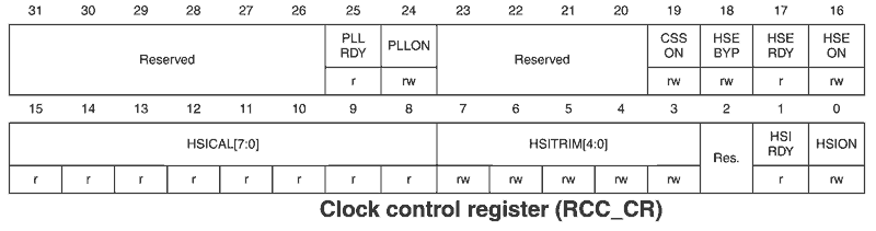
Bits 31:26 Reserved, must be kept at reset value.
Bit 25 PLLRDY: PLL clock ready flag
Set by hardware to indicate that the PLL is locked.
0: PLL unlocked
1: PLL locked
Bit 24 PLLON: PLL enable
Set and cleared by software to enable PLL.
Cleared by hardware when entering Stop or Standby mode. This bit can not be reset if the
PLL clock is used as system clock or is selected to become the system clock.
0: PLL OFF
1: PLL ON
Bits 23:20 Reserved, must be kept at reset value.
Bit 19 CSSON: Clock security system enable
Set and cleared by software to enable the clock security system. When CSSON is set, the
clock detector is enabled by hardware when the HSE oscillator is ready, and disabled by
hardware if a HSE clock failure is detected.
0: Clock detector OFF
1: Clock detector ON (Clock detector ON if the HSE oscillator is ready , OFF if not).
Bit 18 HSEBYP: External high-speed clock bypass
Set and cleared by software to bypass the oscillator with an external clock. The external
clock must be enabled with the HSEON bit set, to be used by the device. The HSEBYP bit
can be written only if the HSE oscillator is disabled.
0: external 4-16 MHz oscillator not bypassed
1: external 4-16 MHz oscillator bypassed with external clockRM0008 Low-, medium-, high- and XL-density reset and clock control (RCC)
Doc ID 13902 Rev 14 97/1096
Bit 17 HSERDY: External high-speed clock ready flag
Set by hardware to indicate that the HSE oscillator is stable. This bit needs 6 cycles of the
HSE oscillator clock to fall down after HSEON reset.
0: HSE oscillator not ready
1: HSE oscillator ready
Bit 16 HSEON: HSE clock enable
Set and cleared by software.
Cleared by hardware to stop the HSE oscillator when entering Stop or Standby mode. This
bit cannot be reset if the HSE oscillator is used directly or indirectly as the system clock.
0: HSE oscillator OFF
1: HSE oscillator ON
Bits 15:8 HSICAL[7:0]: Internal high-speed clock calibration
These bits are initialized automatically at startup.
Bits 7:3 HSITRIM[4:0]: Internal high-speed clock trimming
These bits provide an additional user-programmable trimming value that is added to the
HSICAL[7:0] bits. It can be programmed to adjust to variations in voltage and temperature
that influence the frequency of the internal HSI RC.
The default value is 16, which, when added to the HSICAL value, should trim the HSI to 8
MHz ± 1%. The trimming step (Fhsitrim) is around 40 kHz between two consecutive HSICAL
steps.
Bit 2 Reserved, must be kept at reset value.
Bit 1 HSIRDY: Internal high-speed clock ready flag
Set by hardware to indicate that internal 8 MHz RC oscillator is stable. After the HSION bit is
cleared, HSIRDY goes low after 6 internal 8 MHz RC oscillator clock cycles.
0: internal 8 MHz RC oscillator not ready
1: internal 8 MHz RC oscillator ready
Bit 0 HSION: Internal high-speed clock enable
Set and cleared by software.
Set by hardware to force the internal 8 MHz RC oscillator ON when leaving Stop or Standby
mode or in case of failure of the external 4-16 MHz oscillator used directly or indirectly as
system clock. This bit cannot be reset if the internal 8 MHz RC is used directly or indirectly
as system clock or is selected to become the system clock.
0: internal 8 MHz RC oscillator OFF
1: internal 8 MHz RC oscillator ON


 پاسخ با نقل قول