سلام.در این بخش به بازوهای مکانیکی میپردازیم.

 توجه: این یک موضوع قدیمی است که آخرین پست ارسالی آن مربوط به 4821 روز قبل است . لطفا فقط پاسخ ها ، سوالات و درخواست های 100 درصد مرتبط را به آن ارسال کنید و برای درخواست ها و سوالات جدید موضوع جدیدی را ایجاد کنید


سلام.در این بخش به بازوهای مکانیکی میپردازیم.
ماهیچه ی پنیوماتیکی AIR MUSCLE
بر خلاف عناصر نهایی معمول ،از قبیل سیلندرها و شیرها یا موتورها، گونه های دیگری از محرکهای پنیوماتیکی نیز وجود دارند.
ماهیچه های پنیوماتیکی نوعی محرک انعطاف پذیر هستند که در رباتیک نیز کاربرد داشته و بخوبی می توانند مانند یک ماهیچه ی واقعی عمل کنند.
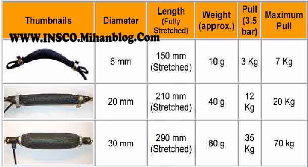
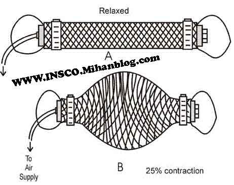
این تجهیزات در سال 1950 توسط J.L. McKibben توسعه یافتند.ماهیچه ی پنیوماتیکی، همانند یک ماهیچه ی زیستی می تواند عمل انقباض را با دمیده شده هوای فشرده به درونش انجام دهد.ابعاد ماهیچه ی پنیوماتیکی و همچنین مقدار فشار هوایی که قرار است به آن تزریق شود مشخص کننده ی میزان باری است که می تواند بکشد یا جا به جا کند.معمولا یک ماهیچه ی پنیوماتیکی می تواند بعد از دمیده شدن هوای فشرده به درونش تا 25 درصد طول خود در حالت عادی ، منقبض شود.
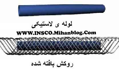
دو جزء اصلی یک ماهیچه ی پنیوماتیکی عبارتند از یک لوله ی لاستیکی داخلی و یک روکش ساخته شده از الیاف پلی استر که به صورت مشبک بافته شده است.با وارد شدن هوا به درون لوله ی لاستیکی ، لوله مانند یک بادکنک منبسط می شود و در نتیجه ی این انبساط ، قطرش زیاد شده و طولش کاهش می یابد.اما چون قرار است که این لوله ،وزن یک بار را تحمل کند، روکش پلی استری جهت استحکام بیشتر در مقابل کشش به کمک آن آمده و از پاره شدن لوله جلوگیری می کند.
روکش چون به صورت شبکه ای بافته شده است و روزنه دار می باشد، به خوبی شکل لوله ی لاستیکی را در انبساط و انقباض ها به خود گرفته و خللی در عملکرد آن وارد نمی کند.
دو سر روکش نیز توسط دو گیره ی محکم ، به لوله ی لاستیکی ثابت شده و یک سمت لوله مسدود می شود. طرف دیگر نیز جهت تغذیه ی هوا توسط فیتینگ به لوله ی هوای پنیوماتیکی متصل می شود. سمتی که مسدود شده بود را می توان توسط پیچ و مهره به بار متصل نمود و به این ترتیب عمل جابجایی بار را توسط آن انجام داد.
درجه آزادی
دستیابی به مفهوم درجه آزادی بدون استفاده از ریاضیات تا اندازه ای دشوار است.واژهء آزادی در عبارت «درجه آزادی» بر آزادی یک عدد در زمینهء داشتن هر مقدار دلخواهی اشاره دارد. اگر از ما بخواهند که، بودن هر محدودیتی،دو عدد را انتخاب کنیم،هر دو عدد آزادی تغییر دارند(هر مقدار دلخواهی را می توانند داشته باشند) ما دو درجه آزادی خواهیم داشت.اگر محدودیتی اعمال شود مانند X=0∑،در این صورت یک درجهء آزادی ما،به خاطر آن محدودیت،از بین خواهد رفت.زیرا اکنون هنگامی که دو عدد را انتخاب می کنیم،تنها یکی از آنها آزادی تغییر دارند.مثلاً اگر 3 را به عنوان اولین عدد برگزینیم،عدد دوم باید 3- باشد.به سبب آن محدودیت X=0∑ عدد دوم آزادی تغییر ندارد،بر همین منوال اگر با رعایت محدودیت مذکور قرار باشد که پنج عدد انتخاب کنیم،چهار درجهء آزادی خواهیم داشت.مثلاً اگر چهار عدد 5-،3،16،8 انتخاب شوند عدد پنجم ناگزیر 22- باید باشد.
محدودیت X=0∑ ممکن است مثالی دور از ذهن به نظر آید. لیکن بعضی از آماره هائی که محاسبه کردیم یک چنین محدودیتی در ساختار خود داشتند.برای مثال هنگامی که SῩ را،بدان صورت که در فرمول t مورد نیاز است،پیدا کردیم؛ ساختار جبری زیر را بکار بردیم:
SῩ=s/√n
محدودیتی که در این ساختار وجود دارد عبارتست از اینکه(Y-Ῡ) ∑ همواره برابر صفر است.برای یافتن آنچه که لازم داریم ،یکی از مقدارهای y مشخص شده است.تمامی yها آزادی تغییر دارند جز این یکی،و درجه آزادی برای SῩ عبارت است از n-1 .به همین خاطر در مورد مساله های مربوط به استفاده از توزیع t برای تعیین اینکه آیا نمونه از جامعه ای با میانگین µ به دست آمده است یا نه، df برابر است با n-1 .
صاحبنظران علم آمار به یکی از دو گونهء زیر درجه آزادی را توضیح می دهند:
1. تعداد درجه های آزادی همواره برابر است با تعداد مشاهدات منهای تعداد رابطه های ضروری که بین این مشاهدات وجود دارد .
۲. تعداد درجهء آزادی هواره برابر است با تعداد مشاهدات اصلی منهای تعداد پارامترهائی که با استفاده از مشاهده های مزبور برآورده شده اند. در مورد SῩ ،یک درجه آزادی کم می شود بدین جهت که Ῡ بعنوان برآوردی از µ به کار رفته است.
مقدمه ای بر حرکت شناسی بازوهای مکانیکی
http://www.his.se/PageFiles/10381/In...kinematics.pdf
ویرایش توسط javad naderi : 12-04-2011 در ساعت 12:16
Introduction to Manipulators
http://www.vgscienta.com/_resources/...troduction.pdf
کمک به طراحي بهتر بازوهاي نانورباتها
پژوهشگران دانشگاه کاشان موفق به محاسبهي مشخصات فيزيکي و مکانيکي نانولولههاي چند جداره کربني و نيتريد- بور شدند که ميتوان از آنها در طراحي بازوهاي نانورباتها استفاده نمود.
انواع پايداريهاي نانولولههاي کربني دو جداره يا چند جداره در محيط الاستيک از مسائل مهمي است که بايد در حرکت چرخشي بازوها هنگام حمل بار حول مفصل يا حول يک نقطهي ثابت، واقع در پيکرهي نانوربات در نظر گرفته شود.
دکتر علي قربانپور آراني، دانشيار گروه مهندسي مکانيک دانشگاه کاشان، در گفتگو با بخش خبري سايت ستاد ويژهي توسعهي فناوري نانو گفت: «يکي از مهمترين وجوه تمايز اين کار با کليهي پژوهشهاي اخير ارايهي مدل پاسترناک است که اين مدل، تأثير نيروهاي برشي اعمالي از جانب محيط الاستيک را بر نانولولههاي کربني دو جداره در تحليل خود در نظر گرفتهاست».
عضو پژوهشکدهي علوم و فناوري نانو دانشگاه کاشان، در ادامه اظهار داشت: «در اين پژوهش، مشخصات فيزيکي و مکانيکي نانولولههاي چند جداره کربني و نيتريد- بور بهدست آمدهاست که از آن ميتوان در طراحي بازوهاي نانوربات استفاده نمود. علاوه بر اين، اين مواد به دليل خاصيت پيزوالکتريکي، ميتوانند به عنوان نانولولههاي هوشمند با استفاده از اعمال ميدان الکتريکي بر آنها، در کنترل چرخش و حرکت انتقالي يا سينماتيک حرکت بازويهاي دست و گردن نانوربات استفاده شوند».
وي با بيان اين مطلب که «در اين کار پژوهشي، پايداري پيچشي نانولولههاي کربني دو جداره بر بستر الاستيک با استفاده از تئوري الاستيسيته غير محلي پوستهي استوانهاي بهدست آمدهاست»، افزود: «با توجه به شکل استوانهاي نانولولهها، از تئوريهاي مکانيک محيطهاي پيوستهي پوستهي استونهاي استفاده شدهاست».
پژوهشگر اين طرح، اضافه کرد: «با توجه به اينکه معمولاً نانولولهها در يک محيط الاستيک بررسي ميشوند، براي در نظر گرفتن نيروهاي اعمالي بر آنها که شامل نيروهاي عمودي و برشي است، از مدلهاي وينکلر(براي نيروي عمودي) و پاسترناک(براي نيروي عمودي و برشي) استفاده کردهايم تا نتايج بهدست آمده دقيقتر باشند».
دکتر قربانپور در ادامه اظهار داشت: «افزايش پايداري پيچشي نانولولهها براي طراحي بازوهاي نانورباتها و نانومتهها بسيار مفيد است. گفتني است که نتيجهي اين تحقيق در طراحي بازوهاي دست يا گردن نانورباتها در برابر پايداري و استحکام پيچشي آنها بسيار قابل کاربرد است».
جزئيات اين پژوهش –که با همکاري آقايان دکتر مهدي محمديمهر، دکتر عليرضا سعيدي، دکتر علي عارفمنش و دکتر هان(از کشور جمهوري خلق چين) انجام شدهاست- در مجلهيJournal of Mechanical Science and Technology (جلد 6، صفحات 1299- 1289، سال 2010) منتشر شدهاست.
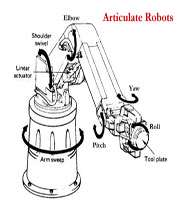
1. اندام های مکانیکی ربات: که شامل بازوهای پیوسته که به صورت لولا به هم متصلند و این مفصل ها به دو صورت عمل می کنند
• دورانی (Revolute )
• منشوری (Prismatic)
هر مفصل و بازو یک درجه آزادی را تشکیل می دهند (Degree of freedom)
در نتیجه اگر شما مثلا n مفصل و n بازو داشته باشیم n درجه آزادی خواهیم داشت این بازوها به بازویی که ربات به وسیله آن به جایی نصب شده متصلند این بازو به بازوی صفر مشهور است و جزء بازو های ربات محسوب نمی شود و در حرکت ربات تاثیری ندارند و به جایی مثلا زمین متصل هستند و توسط این پایه است که مختصات اولیه ربات را می سنجیم این مختصات اولیه به مختصات جهانی معروف است (World coordinate) نحوه شماره گذاری بازوها از بازوی پایه آغاز می شود تا به بازوی انتهایی ادامه می یابد نکته حائز اهمیت آن است که هیچگاه یک ربات یک مدار بسته را تشکیل نمی دهد
2. نیرو محرکه یا راه انداز(Actuator): تولید کننده قدرت و نیروی ربات است که توسط یک کنترل کننده دقیق به کنترل مفصل ها و بازوهای ربات می پردازد که خود شامل 3 نوع می باشد:
• پنوماتیک یا سیستم بادی ( Pneumatic system):
• هیدرولیک یا سیستم روغنی (Hydraulic System)
• سیستم برقی یا الکترونیک سیستم (Electronic System)
هر یک از این سه قسمت به طور مفطل توضیح داده خواهند شد
3. سیستم انتقال نیرو (Transmission system): واسطه ای بین سیستم اندام های مکانیکی و نیرو محرکه است که از محل تولید آن را به یکی از اندام ها منتقل می کند
4. سنسور یا حسگر(Sensor): حکم چشم ربات را دارند که شامل انواع برقی و نوری و .... می باشند
5. دستگاه کنترل یا کامپیوتر ربات (The robot Controller or computer) : در واقع برتری یک ربات از روی سیستم کنترل و میزان هوشمندی آن قابل ارزیابی است
سلام اینم قسمتی از مقاله خودم در مورد بازو های مکانیکی به صورت پی دی اف کردم امیدوارم خوشتون بیاد.
بازوی مکانیکی
بازوهای مکانیکی ماهر (Manipulator) از رابطهای صلبی تشکیل میشوند که به وسیلهٔ مفصلهایی که حرکت نسبی رابطهای مجاور را ممکن میسازند، به یکدیگر اتصال یافتهاند. بازوهای مکانیکی توانایی انجام عملیات از پیش برنامهریزی شدهٔ متنوعی را در صتایع مختلف دارند. بازوهای مکانیکی ماهر در طی سالهای اخیر به شکل قابل ملاحظهای تکمیل یافته و پیشرفت کردهاند. کارکردن با آنها و نیز تعمیر و نگهداریشان آسانتر شده و ارتباط متناسب و بهینهای میان توان٬ کنترلپذیری و مهارت آنها ایجاد گشتهاست.
کاربردهای بازوهای مکانیکی ماهر
در انتهای زنجیره رابطهای تشکیل دهنده بازوی مکانیکی مجری نهایی وجود دارد که بر حسب کاربردی که از ربات انتظار میرود میتواند گیره یا چنگک یا ابزارهای دیگری از جمله لوازم برشکاری و نظیر آن باشد. از این لحاظ بازوهای مکانیکی ماهر متنوعی وجود دارند که گونههای وسیعی و متفاوتی از کاربردهای صنعتی و نیز تحقیاتی را را پوشش میدهند. این کاربردها شامل انجام فعالیتهای متنوع مونتاژ، برشکاری و جوشکاری در خطوط تولید تا انجام عملیات متنوع زیرآبی – نظیر نصب در ربات های زیر دریایی - مانند گرفتن و دنبالکردن کابل یا سیم، و یا محبوس کردن اجسام یا نمونههای پیچیدهای چون برقراریِ اتصالهای خطوط الکتریکی یا هیدرولیکی هستند.
ملاحظات طراحی و ساخت
در انتخاب بازوهای مکانیکی آن چه اهمیت دارد این است که سادهترین نمونهٔ ممکن که بتواند وظیفه محوله را در زمان مطلوب انجام دهد، گزینش گردد. پیچیدگی طراحی ربات در عین افزایش قابلیتهای عملکرد میتواند مشکلاتی در هدایت و نیز اطمینان و دقت دستگاه و نیز تعمیر و نگهداری آن ایجاد نماید. انتخاب و تکمیل مجموعه بازوهای مکانیکی ماهر امر پیچیدهای است و طراح ربات باید نکات فراوانی را لحاظ نماید. تعداد و انواع بازوهای مورد نیاز، محل قرارگیری، نوع کنترلر، محدودهٔ فضای عملکرد٬ حداکثر و حداقل نقطه دسترسی و نوع و ساختار کنترل بازوها توسط کاربر، از آن جملهٔ این موارد است.
مقدمه
بازوی مکانیکی یکی از انواع ربات ها می باشد که در صنعت در کاربردهای مختلفی نظیر صنایع خودروسازی مورد استفاده قرار می گیرد. در این پروژه، یک بازوی مکانیکی با هدف برش اجسام نرم مانند میوه (Stuff Cutter) طراحی و ساخته شده است. بعد از تحقیقات مختلف در مورد انواع بازوهای مکانیکی این طرح انتخاب شد و به مرحله ساخت و اجرا رسید، این دستگاه از دو بازو تشکیل شده است. حرکت هر کدام از بازوها توسط موتور الکتریکی تأمین می شود که نیروی آنها نیز بوسیله چرخ و زنجیر انتقال می یابد . برای ایجاد توانایی برش موازی از حرکت کشویی بازوها استفاده شده است. صفحه آلومینیومی نیز با استفاده از یک میله رزوه شده دندانه کبریتی و یک موتور الکتریکی به جلو و عقب رانده می شود. تیغه ای که برای برش اجسام در نظر گرفته شده بوسیله فنری به انتهای بازوی دوم وصل شده و بازو با حرکت به سمت بالا و پائین بوسیله موتور باعث برش کامل جسم می شود. صفحه نئوپانی که کل دستگاه بر روی آن نصب شده، متحمل وزن دستگاه است. محرک کل دستگاه انرژی الکتریکی است که بوسیله چند کلید قابلیت کنترل آن به فرد کاربر داده می شود. برای کم کردن میزان خطر برای کاربر از موتورهای چرخ و زنجیردار استفاده شده که سرعت بازوها را در یک حد مناسب کنترل می کند و میزان خطر را کاهش می دهد. استفاده از این دستگاه مزایایی نظیر برش دقیق و یک اندازه اجسام را نیز به همراه دارد .
طراحی
طراحی بازو از ایده پردازی شروع شد. در ابتدا ایده های مختلفی بیان شد که هر کدام دارای نکات مثبت و منفی بود.در مرحله ارزیابی نکات مثبت تمام ایده ها در نظر گرفته شده و طرحی مناسب از میان آنها انتخاب گردید. در این مرحله پرسشهای بسیاری مطرح شد که از جمله آنها می توان به ابعاد، شکل، جنس و نحوه کنترل بازوها اشاره کرد.
ابعاد
در انتخاب ابعاد اجزای بازوی ساخته شده نکاتی باید مورد توجه قرار میگرفت. نکته اول مربوط به کنترل حرکت بازوها می باشد. ابعاد اجزای مختلف بازو باید طوری انتخاب می شد که کنترل آن دشوار نگردد. از سوی دیگر در انتخاب ابعاد باید توجه داشت که موتورها و وسایل دیگر نیز باید بر روی آن سوار شوند. ابعاد بازو برای راحتی کار، متناسب با ابعاد بازوی انسان درنظر گرفته شده است تا مانند مکانیزم آن عمل کند.
جنس بازو
جنس بازوها باید از بین فلز، چوب و پلکسی انتخاب می شد. دلیل استفاده نکردن از فلز برای ساخت بازو این بود که پایه دستگاه قادر به تحمل وزن زیاد کار نبود و می شکست. دلیل استفاده نکردن از چوب نیز میزان شکنندگی بالای آن بود.
کنترل بازو
برای قسمت کنترل باید از موتورهایی استفاده می شد که توانایی بالایی برای نگهداری بازوها در مقابل نیروی وزن داشته باشند.بعد از جست و جوی کلی درمورد موتورهای مورد نیاز، این نتیجه حاصل شد که باید از موتورهایی با گشت آورد بالا استفاده شود تا سرعت حرکت بازو را در حد متعادل کنترل کند. برای حرکت کشویی بازو جهت ایجاد برش های موازی از قطعه آلمینیومی دایره شکلی که بر روی میله ای رزوه شده و یک موتور الکتریکی نصب شده، استفاده شد که این ریلی بر روی صفحه نئوپانی(پایه اصلی دستگاه)نصب شد.
ساخت
بازوی برش از پنج بخش اصلی تشکیل شده است، که عبارتند از : بازوها، پایه اصلی، موتورها، پایه متصل به ریل و تیغه برش، که در موارد ذیل به آنها اشاره شده. ابتدا با طراحی آن بر روی کاغذ ابعاد کلی اجزاء بدست آورده شد.
بازوها
با طراحی شکل و ابعاد مورد نظر بر روی پلکسی اولین مرحله ساخت شروع شد، سپس برش بازوها بوسیلة اره عمودبر آغاز و برای کاهش وزن، میان بازوها خالی شد. برای نصب بولبرینگ ها نیز سوراخ هایی در ابتدا و انتهای بازو ایجاد شد و بازوی دوم به انتهای بازوی اول نصب گردید. بعد از این مرحله انتخاب و ساخت پایه اصلی بازوها آغاز شد.
پایه اصلی
ابعاد پایه طوری در نظر گرفته شد که ریل ساخته شده جهت حرکت کشویی بازو به همراه موتور بر روی آن نصب شود. برای تحمل وزن نیز جنس پایه نئوپان انتخاب شد. برای اینکه پیچهای بیرون آمده از زیر پایه موجب برهم زدن تعادل کار نشوند از چهار تکه چوب در چهار طرف پایه استفاده شد تا سطح کار کمی بالا بیاید.
موتورها
در این دستگاه از سه عدد موتور چرخ و زنجیردار استفاده شده که باعث حرکت کشویی و به سمت بالا و پائین بازوها می شوند. همة موتورها بوسیله انرژی الکتریکی کار می کنند. با شروع کار موتور اول، که بر روی پایه نصب شده، میلة رزوه شده درون ریل به چرخش در می آید و حرکت کشویی بازو آغاز می شود. هنگامی که موتور دوم، که بر روی صفحه آلمینیومی متصل به ریل نصب شده، شروع به کار می کند، حرکت به سمت بالا و پائین بازوی اول قابل کنترل می شود و با حرکت سومین موتور نصب شده در محل اتصال بازوی اول و دوم، دومین بازو حرکت خود را به سمت بالا و پائین آغاز می کند.
پایه متصل به ریل
ریل بوسیله دو قطعه چوب مستطیل شکل موازی که بوسیله دو میله آلمینیومی بی حرکت و یک میله رزوه شده دندانه کبریتی به هم متصل شده است، ساخته و بر روی پایه اصلی نصب شده. بازوی اول بوسیلة یک صفحه آلمینیومی که بر روی آن موتور نیز در نظر گرفته شده، برروی دو قطعه نئوپان موازی که بوسیلة حرکت میلة رزوه شده حرکت کشویی دارند، نصب شده. به همین دلیل با حرکت صفحه آلمینیومی بوسیلة ریل، بازو می تواند حرکت کشویی داشته باشد و اجسام را به صورت موازی برش دهد.
تیغه برش
برای برش اجسام به تیغه ای با مقاومت بالا نیاز بود و محل اتصال آن نیز به دسستگاه باید طوری در نظر گرفته می شد که میزان خطر را برای کاربر کاهش دهد. به همین دلیل تیغه به همراه یک فنر به انتهای دومین بازو پیچ و مهره شد. به کار بردن فنر برای نصب تیغه هم بدلیل این بود که جسم باید به طور کلمل بریده می شد و فنر میزان چرخش تیغه را به حد دلخواه کنترل می کند و برای آن قدرت برش دادن کامل جسم را فراهم میاورد.
حضور در عرصه صنعت
رباتها اولين بار در سال 1954 در صنعت به کارگرفته شدند که يک بازوي ربات يا Manipulator نام داشت که تنها داراي 3 درجه آزادي بود
در چندين مقاله به بررسي انواع ربات و بررسي مپالهايي از آنها و عملکرد آنها پرداختيم حال اندکي کاربردهاي صنعتي را بررسي مي نماييم
رباتهاي صنعتي امروزي اکثراً همان بازوي رباتيکي هستند ولي با 6 درجه آزادي و خيلي پيشرفته تر نبست به گذشته کار مي کنند رباتها در صنعت به شيوه ها و روشها و مدلهاي مختلفي به کارگرفته مي شوند.
امروزه ، ?? درصد روباتها ، ربات هاى صنعتى هستند، يعنى ربات هايى كه در كارخانه ها، آزمايشگاه ها، انبارها، نيروگاه ها، بيمارستان ها، و بخش هاى مشابه به كارگرفته مى شوند. در سال هاى قبل، بيشتر رباتهاى صنعتى در كارخانه هاى خودروسازى به كارگرفته مى شدند، ولى امروزه تنها حدود نيمى از رباتهاى موجود در دنيا در كارخانه هاى خودروسازى به كار گرفته مى شوند مصارف رباتها در همه ابعاد زندگى انسان به سرعت در حال گسترش است تا كارهاى سخت و خطرناك را به جاى انسان انجام دهند براى مثال امروزه براى بررسى وضعيت داخلى راكتورها از ربات استفاده مى شود تا تشعشعات راديواكتيو به انسانها صدمه نزند.
برخلاف تصور افسانه اي عمومي از رباتها به عنوان ماشينهاي سيار انسان نما که تقريباً قابليت انجام هر کاري را دارند، بيشتر دستگاههاي رباتيک در مکانهاي ثابتي در کارخانه ها بسته شده اند و در فرايند ساخت با کمک کامپيوتر، اعمال قابليت انعطاف، ولي محدودي را انجام مي دهند چنين دستگاهي حداقل شامل يک کامپيوتر براي نظارت بر اعمال و عملکردهاي و اسباب انجام دهنده عمل مورد نظر، مي باشد علاوه براين، ممکن است حسگرها و تجهيزات جانبي يا ابزاري را که فرمان داشته باشد را نيز دارا باشند
بعضي از رباتها، ماشينهاي مکانيکي نسبتاً ساده اي هستند که کارهاي اختصاصي مانند جوشکاري و يا رنگ افشاني را انجام مي دهند و گاهي سيستم هاي پيچيده تر که بطور همزمان چند کار انجام مي دهند، و يا از دستگاههاي حسي، براي جمع آوري اطلاعات مورد نياز براي کنترل کار خود استفاده مي کنند. حسگرهاي يک ربات ممکن است بازخورد حسي ارائه دهند، طوريکه بتوانند اجسام را برداشته و بدون آسيب زدن، در جاي مناسب قرار دهند. ربات ديگري ممکن است داراي نوعي ديد باشد که عيوب کالاهاي ساخته شده را تشخيص دهد. بعضي از رباتهاي مورد استفاده در ساخت مدارهاي الکترونيکي، پس از مکان يابي ديداري علامتهاي تثبيت مکان بر روي برد، مي توانند اجزا بسيار کوچک را در جاي مناسب قرار دهند. ساده ترين شکل رباهاي سيار، براي رساندن نامه در ساختمانهاي اداري يا جمع آوري و رساندن قطعات در ساخت، دنبال کردن مسير يک کابل قرار گرفته در زير خاک يا يک مسير رنگ شده هستند که هرگاه حسگرهايشان در مسير، يا فردي را پيدا کنند متوقف مي شوند. رباتهاي بسيار پيچيده تر در رديابي محيط هاي نامعين تر مانند معادن استفاده مي شود.
رباتهاى صنعتى زيادى ساخته شد ه اند و انجمن صنايع رباتيك اين تعريف را براى ربات صنعتى ارائه كرد:
«روبات صنعتى يك وسيله چند كاره و با قابليت برنامه ريزى چند باره است كه براى جابه جايى قطعات، مواد، ابزارها با وسايل خاص به وسيله حركات برنامه ريزى شده، براى انجام كارهاى مختلف استفاده مى شود.»
در سال ???? م شركت خودروسازى جنرال موتورز نخستين ربات Unimate را در خط مونتاژ خود به كار گرفت. امروزه کمتر کارخانه اي را مي توان يافت که در آن از ربات استفاده نشود . بازو هاي رباتيکي که بدون استراحت قطعات و محصولات را از نقطه اي به نقطه ي ديگر جا به جا مي کنند . ربات هاي جوشکار ربات هاي رنگرز ربات هاي بسته بند ربات هاي تراشکار ربات هاي چاپگر ربات هاي کنترل کيفيت ربات ها سوراخکار ربات هاي کنترل دما ربات هاي هشدار دهنده نشت گاز ربات هاي غربال سانتريفوژ هاي خودکار و … همگي نمونه هايي از ربات ها در کارخانه ها هستند .
کارخانه ها براي افزايش سرعت و کيفيت و دقت و هزينه پايين تر به سمت رباتيکي کردن تمامي قسمت هاي کارخانه پيش مي روند و در بعضي از قسمت ها که براي انسان خطرناک است مانند جوشکاري و رنگ پاشي و سموم شيميايي و …. ناچار به استفاده از ربات مي شوند
امروزه استفاده از رباتها , اتوماسيونهاي غير قابل انکار و معرفي شده اي هستند براي تمام صنايع و کارخانه ها، به طوري که کارخانه ها روز به روز به اين سمت روي مي آورند دليلش هم مشخص است زيرا بازده اي بهتر و سرعت و دقت بيشتر و کم هزينه بودن ديگر خصوصيات مورد انتظار را به ارمغان مي آورد.
Manipulator Kinematic Control: End-Effector
The Canadian built Special Purpose Dexterous Manipulator (SPDM) is one of many space manipulators available to NASA. For analysis, planning, and training, simulations of this manipulator are necessary. The end-effector of each SPDM arm is the ORU Tool Changeout Mechanism (OTCM). Simplify Robotics developed the simulation math models which kinematically mimic the behavior of the OTCMs. The math models were developed in C using the Trick simulation development environment.

Manipulators & Goniometer Catalog Download (PDF)
http://www.eurotekgmbh.de/Eurotek/me...q8n0c3clcljp23
METHODS FOR MOUNTING MANIPULATORS ON MOBILE SELF-PROGRAMMING ROBOTECHNICAL COMPLEXES
Abstract: After the robotized manufacturing units and the flexible robotized production systems, mobile self-programming robotechnical complexes (MSRC) get recognition in real life. Their application gets out of the production sphere to enter all other spheres of modern life.
MSRC construction is a big and complex task. One of the key moments in construction is the method for linking separate mechanical systems.
In this paper are shown some methods that go beyond the traditional methods for mounting manipulators in the production cells and flexible robotized production systems.
�. Introduction. Traditional problems with attaching (funding) manipulators
Attaching (funding) manipulators is not a big and complicated engineering problem.
Usually, the manipulator has a big and heavy plate (Fig. 1) that can be fastened with screws to the funda-ment. In the general case, the fulcrum reactions that are applied through the plate are as follows:
SX=0 (1)
SY=0
SZ=0
SMx=0
SMy=0
SMz=0
This is true when the manipulator is funded to the ground (floor) and the Z-axis is perpendicular to the plate.
After static load it is turn of dynamic attachment check. From the motion rules:
S=f(x,y,z,t) (2)
after consecutive differentiation in time domain we get the following speed and acceleration equations for the manipulator movement:
S`= dS/dt=f``(x,y,z,t) (3)
S``= dS`/dt=f```(x,y,z,t) (4)
Knowing the rules of movement, we can calculate the values for the speed and acceleration for any point within the range of operation of the manipulator.
After multiplying the corresponding moving masses, we can calculate the dynamic system loads:
F=m.S`` (5)
These dynamic system loads and the static ones from formula (1) can give us the full system loads, there-fore we can calculate the loads over the plate base.
Having these equations we can now calculate the mounting elements and the whole fundament.
We have analogical calculations in case the manipulator is attached to a wall or ceiling.
Precise manipulator funding calculations are needed for vibration damping and fundament vibration ab-sorption. The fundament should be enlarged or has its shape changed in case vibration damping and absorption are insufficient. In these cases the main factors relied upon are the static vibration damping and absorption.
When mounting a manipulator over a mobile platform the load equations (1) and (5) are also applicable. Mounting elements are calculated accordingly. Manipulator loads are transferred through the platform to the traction system. In this way the mobile element is also under the manipulator loads (1) and (5), along all other loads. Vibration damping and vibration level control is maintained using dampers and dynamic vibration calmer.
��. Other methods and places for manipulator funding
Technology progress requires the funding (attachment or hanging) of manipulators except to the already listed cases - floor, wall, ceiling or mobile platform, but also to other mechanisms or other mechanism sections.
Mechanical systems, that pose requirements for manipulator funding, are robotechnical complexes.
In the common case these robotechnical complexes are mobile and include more than one manipulator, as well as a variety of other mechanisms, interconnected with each other. In particular, the robotechnical complex may be stationary and attached (funded) to a floor, a wall or a ceiling. This doesn't mean that it is equal to the simple manipulators, although the funding is achieved the same way.
Further on it this paper we will consider the mobile self-programming robotechnical complexes (MSRC). The term self-programming denotes that these complexes are designed to operate in environments that are not previously familiar to manipulator constructors. In essence, they are constructed to operate in conditions that the constructor has very limited set of data about, or no data at all. That is why, after the dynamic load balance check, it is necessary to evaluate the endurance of possible shocks or shock loads on all axes.
Mounting manipulators on such robotechnical complexes can be reviewed in two aspects:
1. Manipulator mounting on a single MSRC stage;
2. Manipulator mounting on multiple (two or more) MSRC stages.
1) Manipulator mounting on a single MSRC stage has much in common with mounting over a mobile platform.
The mobile platform can be viewed as a single MSRC stage, that has one or more manipulators attached. The mobile platform is usually a single-corpus detail, to which all other nodes and aggregates are attached, in-cluding manipulators.
Due to its greater own mass, compared to other details, and its greater dimensions, it has greater momen-tum, which helps other aggregates' vibration damping and absorption.
It is one of the characteristics of these types of mounting. They are used with most of the existing mobile robotechnical complexes (Fig. 2a).
In nature this type of mounting can be observed with insects (Fig. 2b). The cuticle, forming one sector of the insect body is actually the mobile platform. It usually has two or more pairs of manipulators, used by the liv-ing organism as limbs.
As little as manipulators may be, compared to the mobile platform, the load they produce influences its movement, especially the dynamic components (5). That is why, in these cases a dynamic balance of the system is required.
The methods are:
1. Minimizing the movement of the composite center of gravity using additional movement of the unused manipulator
2. Minimizing the movement of the composite center of gravity using simultaneous synchronized manipu-lator pair movement
Fig.2 b) and c) come to show that manipulators are not attached to the mobile platform using bolts, but us-ing some mechanisms instead. At Fig. 2 b) this mechanism gives the preliminary orientation of the first manipu-lator stage (insect's leg) cx, while in fig. 2 c) this mechanism moves the manipulator vertically.
These mechanisms are called connection mechanisms. They increase the manipulator operation zone, and also transform the reactions (1), as well as the dynamic loads (5) into power loads, suitable for transfer to other mechanisms. In this particular case, it is the mobile platform and the mechanisms for its movement.
The problem formulated here is reduced to a simple engineering task for calculating the mobile machine, additionally loaded with manipulator base tensions.
2) Another interesting manipulator mounting is the so called soft mounting.
Fig. 3
It is a type of mounting, in which all possible reactions that may arise in manipulator fundament are ab-sorbed by the engine. With this type of mounting it is not possible to connect a solid elastic manipulator element to a carrying mechanism stage.
This is usually a six-stage mounting, no matter if some of the stages is insignificantly loaded compared to the others.
This type of mounting is very common in nature with marine creatures. It is the way of mounting used to connect the fins to the common fish body mechanisms. In this way fin bones have no joint connections with the bones, building fish spinal structure.
The mechanism interconnecting the manipulator with the carrying mechanism is actually the linking ele-ment for the manipulator mounting. If the carrying mechanism is of the mobile platform type, the problem can be brought down to the first type of mounting, described previously. If the carrying mechanism is not of the mo-bile platform type, the problem is brought to a problem type, described further in the paper.
In this case the calculations for the linking mechanism itself are brought down to the platform problem ro-bot type.
Currently, this king of mounting is not widely applied in practice, except for some types of measuring stands, acting as tactile sensors.
3) The other big mounting class deals with mounting manipulators on carrier mechanism stages.
The carrier mechanism can be single or multiple stage, working together as a whole under certain condi-tions - Fig .4 a) and b).
If the mechanisms are more than one, chained together to produce a certain kind of movement, they can be ap-proximated as separate chain stages, as shown on Fig. 4 c). This approximation is completely conditional
The problem here is to mount a manipulator with a certain kinematical structure to such chain.
Based on the methods for mounting in the previous two cases, we can say, that the connection between the two kinematical chains will be realized with an interconnecting mechanism. It can be based on one ore more stages, corresponding to Fig. 5, but it is methodologically easier to assume that it is connected to one of the stages and only controlled by other stages' movemen
Of course, Fig. 5. shows planar types of lever mechanisms, but the problem is similar with the other types of planar and spatial mechanisms
Carrying mechanisms are constructed to work synchronously, while their stages conduct certain move-ments, obeying certain movement rule:
S�=f(x,y,z,t) (6)
On the other hand, we have certain operation zone that the manipulator we wish to mount has to cover. This operation zone can only be covered if the base of the chosen manipulator conducts certain movement:
S��=f(x,y,z,t) (7)
In this case the connecting mechanism synthesis problem is completely definable. Having the carrying mechanism and outer connecting mechanism stage movement rules, we can define the transfer function:
(8)
Having the kinematical plan of the carrying mechanism and the transfer function of the connecting mechanism, we can synthesize the connecting mechanism and determine the force transformations (1) and (5) from the manipulator base to the outer points of the connecting mechanism or the stages of the carrying mecha-nism. Therefore we can determine the distribution of the load upon the chain of carrying mechanisms, coming from the manipulator and the connecting mechanism. On Fig. 5 are shown mechanisms, ending with point of mounting the manipulator.
It is completely acceptable to mount manipulators on a line or a plane in certain situations.
In the cases of line mounting, we need to pay attention to its position in space, as well as its direction.
In the case of mounting to a plane, we have planar movement as well as its orientation in space.
In nature this type of manipulator mounting is very common. In living creatures anatomy, mainly in verte-brates' anatomy, this type of mounting defines the manipulative girdles - the pectoral and pelvic girdles, which carry the limbs (Fig. 7).
The pelvic girdle is a living example how can the connecting mechanism turn into a segment line, con-nected to a stage of the carrying mechanism.
The manipulator mounting on carrying mechanical systems is an important branch in the synthesis and construction of MSRC. The movement of these complexes, especially of zoological or humanoid type is a sum of the movements of the separate mechanical systems in their structure.
Starting with the main mechanical struc-ture (the spine with the living organisms), that sets the type of movement, go through the connecting mecha-nisms, manipulative systems and finish with the orienting and catching devices.
Smov.= SSmech. (9)
In practice it is preferable to use additional mechanisms between the connecting mechanism and manipu-lator mounting mechanisms - the so called adaptors for fast manipulator change, which overleaps the living or-ganisms' natural abilities.
ویرایش توسط javad naderi : 15-04-2011 در ساعت 03:03
Singularity Analysis of Parallel Manipulators
Parallel manipulators are characterized by having a base platform and a top platform connected by serial chains. The first class of parallel manipulators studied had serial chains composed of a passive universal joint, a prismatic actuator and a passive spherical joint, and are called Stewart or Gough platforms.
More general serial chains can be used between the base and top platform in order to provide an alternative to prismatic actuators. The parallel architecture used in our hand controller design features pantograph linkages instead of prismatic joints.
A singularity occurs in general when the forces acting on the top platform of the manipulator no longer constrain it. This causes problems for motion control and path planning algorithms since it is mathematically equivalent to dividing by zero.
Singularity Analysis Using Line Geometry
Passive spherical joints are almost always used in 6dof parallel manipulators. Because of this, only pure forces can be transmitted to the top platform. These forces are produced by actuating either the prismatic actuators or one of the lower revolute joints of the serial chain. These forces have distinct LINES OF ACTION through the spherical joints and can be used as a starting point for analyzing when the platform Jacobian becomes singular.
Standard analytical techniques for identifying when a parallel manipulator is at a singularity lead to extremely large equations that are difficult if not impossible to analyze fully. Because of this limitation, researchers have used line geometry to study parallel manipulator singularities.
The basic idea is that the lines of action of the forces acting on the top platform form a line system with a certain rank. If the total rank of the system is LESS than 6, the platform configuration is singular. The following figure shows how lines can form systems of a certain rank.
A parallel manipulator looses rank (is at a singularity) if it has at least N+1 lines belonging to an N-system of lines where n can be anywhere from 1 to 5. We can identify when this occurs by matching key geometric features of line systems with the geometric configuration of the lines of force on the manipulator. In the following examples we highlight some of these key features.
EXAMPLES
A singularity occurs in the hand controller whenever the lines of action of the forces due to the actuators belong to a rank deficient system of lines. These forces act along the upper links of the pantograph linkages. By comparing the configurations of lines with the systems in the line system chart, we can determine the singular configurations by inspection and geometric reasoning.
In each of the following examples, the hand controller architecture is pictured in a singular configuration where a subset of lines belongs to a rank deficient system indicated by its type in the above table. In each case, the top platform cannot be completely constrained by the forces produced by the actuators.
Example of Type 5b
The hand controller has a type 5b singularity whenever the lines along the upper bars of all 6 pantograph linkages intersect a common line. In this case we have 6 lines that lie on a rank 5 system of lines.
Example of Type 4d
The hand controller has a type 4d singularity when it has the following configuration. The key geometric feature are that one of the spherical joints lies in the plane defined by a second pantograph linkage, and a third pantograph force intersects the center of that spherical joint. In this case we have 5 lines belonging to a rank 4 system of lines.
Type 3c
The hand controller has a type 3c singularity whenever the lines of force from two different pantograph linkages intersect the spherical joint of a third one. In this case we have 4 lines belonging to a rank 3 system of lines
Singularity Analysis Using Clifford Algebra Elements
Another approach to singularity analysis is to convert the constraint equations into a special algebraic form using elements of Clifford Algebras. The constraints imposed on the top platform by the serial sub chains define algebraic surfaces and singularities occur when those surfaces intersect in special ways. The set of all singular configurations of the manipulator form another surface which we call a singularity surface. The geometry of the parallel manipulator architecture is directly related to the geometry of the resulting singularity surface.
Consider the two planar parallel architectures shown in the following figure. The first is characterized by having similar base and top platform triangles and is called a proportional planar parallel manipulator. The second is characterized by having those triangles collapse onto a line and is called an in-line planar parallel manipulator.
The loci of singularities of these two manipulators can be defined algebraically. In each case we get what is called a quartic surface, where the geometric characteristics of the surface are unique to each type of planar manipulator. The usefulness of this type of formulation is that if we want to move the manipulator from one position to another without moving through a singularity, the whole path of the manipulator must be on one side of the singularity surface
Singularity surface of a proportional planar parallel manipulator
Singularity surface of an in-line planar parallel manipulator

Kinematics, Dynamics and Design of Parallel Manipulators
It is known that parallel manipulators have higher payload capacity, more rigidity and better dynamic performance as compared to serial manipulators. However, parallel manipulators themselves suffer from small workspaces and low dexterity. To overcome the foregoing drawbacks we combine the concepts of redundancy and modularity in the process of kinematic design and obtain a new class of hybrid parallel manipulators. To this end, some novel designs pertaining to the foregoing class, with a complete analysis of their associated kinematic problems, have been presented (see Fig. ). We are now attempting to write a general symbolic routine to perform the kinematic analysis automatically. Also, studies have been conducted on the direct kinematics of general parallel manipulators. As a result, a new formulation was presented whereby the positioning and orientation problems are decoupled. A real-time implementation using extra-sensor data has been accomplished. We are now studying algorithms for the dynamics of these manipulators.
K. Etemadi--Zanganeh, J. Angeles
A novel redundant parallel manipulator
 مجوز های ارسال و ویرایش

 پاسخ با نقل قول